- ENGINE & MACHINERY SOLUTIONS
- TELEMETRY SOLUTIONS
- DEBARKERS
- BRANDS
- POPULAR PARTS
- ENGINE & MACHINERY SOLUTIONS
- TELEMETRY SOLUTIONS
- DEBARKERS
- BRANDS
- POPULAR PARTS
- About Us
- Contact Us
- News
- Project Gallery
- Explore Our Capabilities
- +61 3 9358 5555
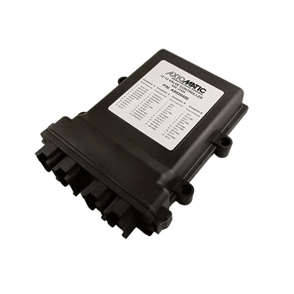
12 Inputs, 12 Outputs, SAE J1939, Multi-functional
The valve controller provides precise, repeatable control of 8 proportional or on/off solenoids plus 4 on/off solenoids. It is networked on a SAE J1939 bus. Up to 7 signal inputs and 5 digital inputs are accepted for interface to a PLC, Engine Control Module, switches, command potentiometers or sensors. It operates with 12Vdc or 24Vdc power.
The controller has altogether twelve inputs, which are divided into Universal and Digital Inputs. Universal Inputs can be configured to measure voltage, current or digital signal and Digital Inputs can be configured to measure digital signals. In addition, Universal Inputs 1 to 6 can be configured to measure resistance. Frequency, signal pulse width and pulse count can be measured with Universal Inputs 1, 3, 5, 7 and Digital Inputs 1, 3, 5. Designed for rugged machine applications, it features an IP67 rating, CE marking and is suitable for high vibration installations.
Controller settings are user configurable to suit many applications. Configuration is via a Windows-based Electronic Assistant® configuration tool and an USB-CAN converter. From the control logic perspective, the AX020400 consists of a set of internal functional blocks, which can be individually configured. Using the input function block, each input can be configured to measure the input value, and send the data to a SAE J1939 network. With the output function block, any output on the controller can be configured to use any of the onboard inputs as either a control signal or an enable signal, instead of taking the control information from the CAN bus.
The PID Control Function Block is associated with the proportional output type. The Lookup Table Function Block is used to give output response up to 10 slopes per input. If more than 10 slopes are needed then the Programmable Logic Function Block is used to combine up to 3 tables to generate up to 30 slopes. The Math Function Blocks allow the user to define basic algorithms. The DTC React Function Block allows for a received DTC from another device on the CAN network to disable an output or act as an input to a function block. Diagnostics messages are provided over the CAN network for the status of inputs or outputs and are configurable via the Diagnostic Function Block.
The model operates with Simulink® for easy graphical programming in a model based simulation and development environment. The functional blocks have been readily implemented into the Simulink model. With the Simulink model it is possible for a customer to easily modify functional blocks to produce their own custom software.
For example, input and CAN message connections can be altered, transfer functions can be added between inputs and CAN messages and initial values for functional block set points can be configured. The Axiomatic Hardware Interface Library (HWIL) is provided for this purpose. For simulating models using Axiomatic HWIL, licenses for Simulink® and Stateflow® are required. Code generation also requires the Simulink Coder™ license.
Applications:
Features:
Collections: J1939 I/O CONTROLLERS